Description
Equipment Overview
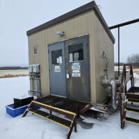
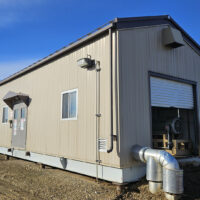
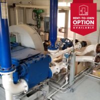
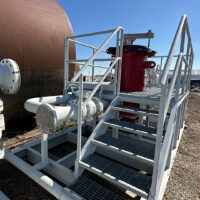
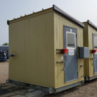
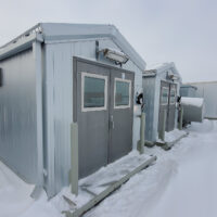
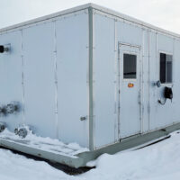
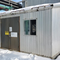
With just over a year of runtime on these two dual 200HP water injection / water disposal pump packages – our internal pump inspection showed them in great shape and could run as-is with spare parts on hand. The pumps can do around 350GPM/1900m3/day at 1000psi and at 1440psi it will do ~230GPM/1250m3/day. The fluid end and discharge piping are good for 900# (~2100psi) giving tons of flexibility for other applications. The building is only 10’4” in height and 12’ wide – with top mount motors the package has lots of space to access everything, the building size is compact and easy to transport. As shown in the photos, these are in great shape and are a low-price buy – saving you 60% vs buying NEW. It’s rare to find available pump setups like these!
403-819-3906
Pump Package Specifications
Main Pump, Motor & Equipment
Quintuplex Pumps:
- Two (2) Aplex MA-240L Quintuplex Pumps
- Maximum Continuous RPM Rating: 450RPM
- 6″ 150# FF Suction Connection
- 3″ 900# FF Discharge Connection
- Rated for 240HP Continuous Duty
- Sheave Kit and V-Belt Drive
- Belt Guards
- 5 Feed Lubricators w/ 55 Gal Oil Reservoir
- Suction & Discharge 600cu In Stabilizers
- Mounted on sub-assemblies and attached to main skid
Quintuplex Pump Motors:
- Two (2) Brook Crompton 200 HP Electric Motors
- 447TZ Frame, TEFC
- 1785 RPM
- 460/3/60VAC
Pump Notes:
Pumps are in excellent condition as verified by our own internal inspection. Pumps would require only minor parts but could be run as is if it needed to.
The package ran for just under one year prior to shutdown.
Charge Pumps:
- Two (2) Eagle ANSI A-100M
- 3″ x 2″ x 10″ S.S.
- 180 GPM @ 97 Feet ( 42 PSI)
- 1800 RPM
- Mechanical seal with Plan 11 Flush
Charge Pump Motors:
- Two (2) TECO 10 HP
- TEFC 215T Frame
- 1800 RPM
- 460/3/60 VAC
- Inverter Duty Rated
- Drive Coupling and Guard
Aplex MA240L Quintuplex Pump Curve Performance
Instrumentation
- PI-200/210 Discharge pressure Indicator (0-3000 PSI)
- PIT-200/210 Discharge Transmitters
- PI-100/110 Suction pressure indicator (0-150 PSI)
- PIT-100/110 Suction pressure transmitter
- VSH-200/210 High Vibration Switch
- LSL-200/210 Murphy EX Low Oil Level Shutdown
- LSH-100 Sealed Sump Level Switch
- We PCV-100/200 Startup Bypass valves with Actuator
Process Piping
Filter Vessels:
- Two (2) Fil-Trex 3 Bag Fiter Vessels
- MAWP 150 PSI @ 250F
- Rated @ 165 GPM
- Complete with 4″ Bypass piping for Filter change
- 4″ 150 RF Flanges Inlet/Outlet
Suction Piping:
- 6” 150# Suction Inlet
- Remainder for Suction Piping 3″ & 6″ to Each Pump
- 3″ Spools for Stabilizer Mounting
- Internally Coated
Drain Piping:
- All process piping drains go to sealed sump via threaded drain piping
- Filter drain piping currently in place (absent of filters)
- Pump stuffing boxes drain into open Sump
Discharge Piping:
- Each individual discharge line exits the plunger pump into a 3” 900 ANSI rated line. The discharge stabilizers are located directly after the plunger pump discharge.
- The PSV and automated startup bypass valve are located before the discharge header. There is an Isolation and check valve prior to connecting to the discharge header from each pump individual discharge line, to prevent back flow possibilities.
- PSV and start-up bypass piping discharge into vent/return piping to skid edge
- Drain valves to drain sump
- All supports are mounted on structural skid members
- All supports are secured by clamp style tie-downs
Building & Electrical
Skid:
- 10’ W x 40’ L Skid and Building
- ¼” Checker Plate Flooring
- 2” Drip Lip Around Skid
- One (1) Open Sump w/ drain to skid edge
- Sump: High Level Sump Switch
Building:
- Shed Style Foam Core panel Building
- Four (4) 12” x 18” Louvers w/ closers
- Two (2) Double Man Doors
- One (1) Single Man Door
- 3” Fire Retardant Spray Foam Under skid Insulation
Electrical:
- Six (6) Interior Lights w/ Switches
- Two (2) Exterior Lights w/ Switches
- Two (2) LEL Gas Detection Units
- One (1) 120V Electrical Receptacle
- Two (2) ESD Buttons Exterior
- Two (2) RUFFNECK XP heaters w/ thermostats
End Devices Connected to JB’s:
- Two (2) pressure transmitters – Suction
- Two (2) pressure transmitters – Discharge
- Two (2) vibration switch (power end)
- Two (2) oil level switch low (power end)
- One (1) sump level switch
- Included: Rigid aluminum conduit and steel uni-strut used throughout
- Lamicoids for all switches, junction box’s, and ESD’s
- Bottom entry into junction boxes for all conduits
Drawings
Download drawings here.